
It’s time to recover!
- B2D2

- Apr 7, 2020
- 2 min read
In these times of viruses and quarantines, thoughts about recovery might flood our minds. That’s why this week we are talking about B2D2’s Recovery Unit.
Until now, we have told you what our experiment will consist of, how we are planning to perform it and even talked about some of the mechanics and electronics involved. But what will happen once we launch and perform our measurements? We have to retrieve the experiment somewhere in Sweden’s cold north, above the Arctic Circle. We can not know where our Free Falling Unit will land in the vast area. That is why we have to develop and implement a successful Recovery Unit, otherwise the experiment will be lost.
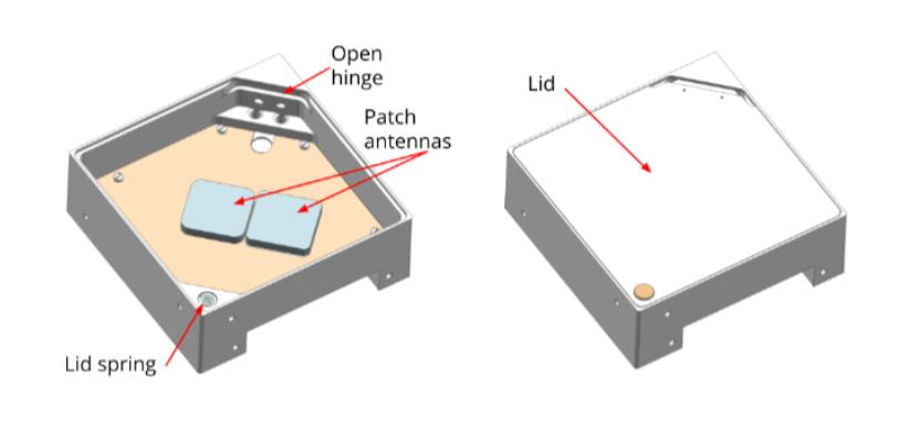
The Recovery Unit consists of a localization system and a Parachute Deployment system. Both are cased in an aluminum structure divided by a mid plane. In the upper side of the Recovery Unit the Parachute deployment system and the antennas are located, while the localization system and electronics are placed in the lower compartment.
Parachute Deployment System:
When the 5 km altitude is reached, when descending, a pressure sensor will send the information to the Recovery Unit FPGA, which in turn will trigger a thermal cutter that will open the Recovery Unit lid and the parachute will be deployed. The thermal cutter is a metal wire that gets hot and melts the nylon string that keeps the lid closed.
The parachute is made of a special material that is transparent to our antennas, so it will not present an issue even if we place it on top of them.
The parachute deployment system will help to reduce the landing impact, but that doesn’t guarantee that we will be able to find it. This is where the localization system comes into play.

Localization System:
Right after ejection, a GPS antenna will start receiving GPS raw data. Since at the altitudes that the FFU will be operating commercial GPS don’t work, we will have to use a special GPS front end. The GPS signal will then be processed and sent to a VHF antenna to transmit the FFU position. Once the FFU is descending and the 5km altitude limit is reached the FPGA will redirect the GPS signal from the special GPS front end to a commercial GPS front end, through a RF switch. The position will be also sent to a Globalstar antenna for transmission. This allows us to receive the FFU position signal through 2 different channels: VHF and Globalstar network.
The Recovery Unit will keep transmitting the position even some time after landing, then the rescue team, coming in a helicopter, will intercept this signal and find our experiment.
All these tasks are performed by several circuits located in 3 PCBs. The motherboard will handle the thermal cutter, the VHF and Globalstar transmission as well the interface to the different units in the experiment. A GPS PCB will be responsible for all the GPS raw signal processing. Finally, the Data hub will work as the Recovery Unit computer, receiving information from all the subsystems and giving commands to them.

Remember to visit out our website: www.b2d2.se, our Facebook page, and our instagram accounts. Next stop on the B2D2 train: More Mechanics!
T-11 Months


Comments